This shield was designed with no particular project in mind. It aims to be useful for both automatic and keypad-operated antenna selectors in general. This is just hardware, providing slightly more than a set of ten relay drivers, but there are many projects/sketches on the Internet (including this blog) that could be easily adapted to work with it. The shield could also help build other Arduino-based devices that will switch multiple loads on and off and may have nothing to do with amateur radio.

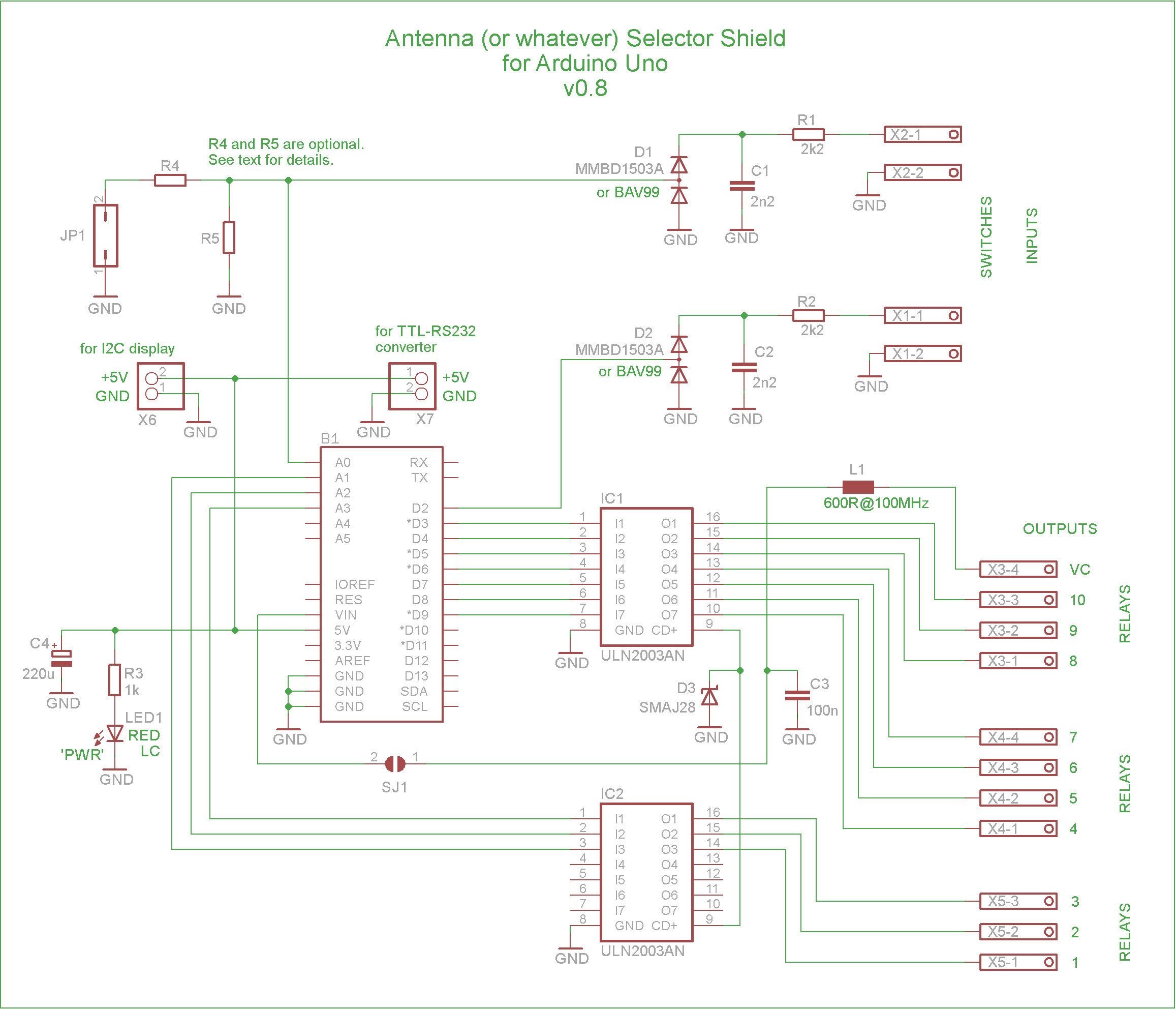
– If the VC contact is not used, L1 and C3 can be omitted. If L1 is replaced by a resistor, the value of this resistor (R) should be very low, 0 ohms to 5 ohms. This will limit the voltage drop across the resistor, which is equal to the relay coil current times R.
– If all the relay coils are fitted with flyback diodes, D3 could be omitted.
– C4 (size D tantalum) is more useful or needed if the load on the +5V power rail is high or ADC is used.
– In fact, pretty much anything could be omitted or adjusted for the specific design – provided that you know what you’re doing.
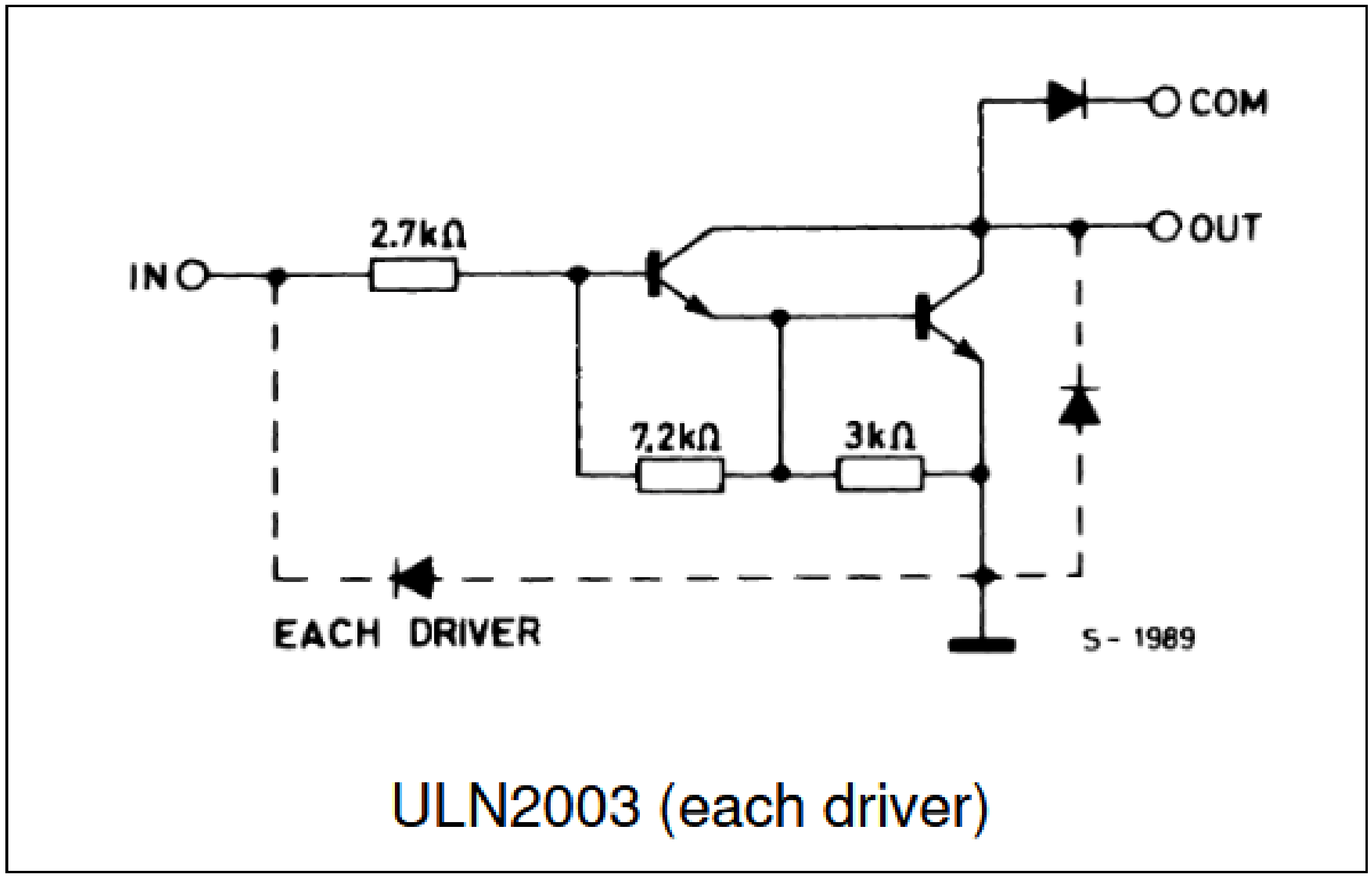
The ULN2003 IC is an array of seven low-side Darlington-pair drivers. On this shield there are ten available drivers in total and they can be controlled by Arduino. So there can be ten antenna-switching relays. Each relay coil should be connected between a driver (‘OUT’ in the picture) and the positive power rail, and the driver conducts current to GND when turned on. The introduced voltage drop can be up to 1V, which by itself shouldn’t present a problem for 12V relays. Check the relays datasheet anyway.
The way the power is supplied is important: if the project requires an LC display with a backlight and some other peripheral devices each drawing 50 or 100 mA on +5V – the Arduino Uno and the shield(s) should be supplied with +5V from an external and sufficiently powerful source through the USB connector on the Arduino Uno. In this scenario, the common positive voltage for the relay coils will generally come from a separate source (+24V max) that shares a common ground with the Arduino board. DO NOT bridge the SMD jumper SJ1.
On the other hand, if the total power consumption is low, the Arduino Uno and the attached devices can be powered from the 5V regulator on the Arduino board, i.e by connecting 9…12V to Vin. In that case, provided that you use appropriate relays, you can bridge the SMD jumper SJ1 and then use the voltage from the VC (Voltage Common) contact to power the relays. It’s “Voltage Common” because it’s common for all the relays. VC will basically be the same as Vin of the board, only a simple RF filter in between to protect Vin from possible RF noise collected by a long VC wire.
There are two inputs intended for simple switches (at D2 and A0), as well as a jumper at A0, because someone may just need a jumper instead of the second switch. These inputs at D2 and A0 are adequately protected against overvoltage, reverse polarity and RFI. When a switch is closed, the respective pin is at GND.
The UART, I2C and SPI pins of the uCU are all available for either their specific functions or for use as general I/O pins.

Example 1:
This early prototype, on a breadboard, was successfully tested as a CAT-controlled automatic antenna selector. It worked with the Kenwood TS-590 and Yaesu FT-991A. Although their CAT command sets are somewhat different, the commands that are actually needed for this kind of project are quite similar. Using CAT/RS-232 for band data input, and not Yaesu-style BCD codes, certainly is more fiddly but allows for more flexibility. For example, you can choose from two antennas on the same band – one on VFO A and the other on VFO B. By the way, a typical TTL-RS232 converter should draw less than 10 mA when active, especially at low bit rates. Also this is where I learned that you can use 3.5mm screw terminal blocks on 2.5mm hole grid if you rotate them 45º.
For how to connect an Arduino board to the radio’s CAT port via RS-232, see this picture:
https://yu2zz.com/wp-content/uploads/2024/09/01.png
But, first of all, consult the radio’s CAT manual carefully.
A similarly basic program for Yaesu BCD would be almost trivial.

Example 2 (a work in progress):
It’s a three-board stack: there is a USB Host Shield between the Uno and the selector shield. It lets you plug in a fancy USB keypad with any number of keys, black or white, with LEDs etc. It uses the Uno’s four SPI pins (D10-D13) and this particular variant also needs pin D9 for its own purposes, so the Arduino sketch must avoid D9 and especially must not set it as output, or the USB Host Shield might get damaged. I also cut the trace between D9 and the pin 7 of the ULN2003 on the selector shield. An LCD is connected via I2C (pins A4, A5). We still have to decide on how the names for the antennas will be changed: either via a normal PC keyboard or via Bluetooth (HC-05) and a generic terminal app on the phone. (BTW, topic-adjacent: this.)
The receive antenna and the transmit antenna can be selected independently (for now). There are five of them in total. Because of the long cable between the shield and the 12V relays in the attic, a +15V source was chosen to power both the relay coils and a DC/DC converter that provides +5V for the electronics.
One of the screw terminal blocks is omitted here because it is not really needed, so there’s also no need for the second ULN2003, so three more I/O pins are now available to the program.
Regarding the USB keypad, I found this quite helpful:
https://www.youtube.com/watch?v=EpXxh4k4NW8
A matrix keypad, on the other hand, can be connected directly to the Arduino Uno. It is cheaper, simpler to implement and saves power. It would take more pins – in principle – but there is also a clever way to connect a matrix keypad to a single analog pin on the Arduino. Individual momentary switches could also be used.


But, with ‘stacking headers’ and their extra-long pins, the outer rows of holes/pads are left available for soldering connections, which is quite convenient. Stacking headers also provide more clearance between the boards.
Ten Arduino pins control ten relays:
A1 — Relay 1
A2 — Relay 2
A3 — Relay 3
D9 — Relay 4
D8 — Relay 5
D7 — Relay 6
D6 — Relay 7
D5 — Relay 8
D4 — Relay 9
D3 — Relay 10
The protected inputs are at:
D2
A0
A0 can be used in multiple ways (one at a time) – which is in principle true for any Arduino pin – but here A0 is specifically intended for multiple usage scenarios:
Only if you need to use A0 as an analog input for, say, the Icom ‘Band Voltage’, both R4 and R5 will be needed, and their values will be critical, as they will form the necessary voltage divider at the input. Also it would be good to add a 10-100 nF capacitor in parallel to R5. The jumper (JP1) pins will be used as input terminals for the ‘Band Voltage’.
Otherwise:
If you don’t need the jumper JP1 at A0, leave the two pins of JP1 unconnected. R4 and R5 are irrelevant and you don’t need them.
If you intend to use jumper JP1, install R4 with a value of 0Ω or some other low value, or just bridge the gap between the R4 pads with solder. Leave the place for R5 empty.
And, obviously, if you and your program use the protected switch input at A0, you can’t use A0 for anything else. So leave the two pins of JP1 unconnected. Also, in that case, R5 must be removed and R4 is irrelevant.
Finally, you can choose to access and use both D2 and A0 directly, bypassing or omitting the protection circuits altogether.
Antenna selectors should be housed in grounded metal enclosures and completely disconnected during stormy weather.

See Arduino sketch at
https://yu2zz.com/2023/07/11/cat-to-bcd-for-kenwood-ts-590-with-arduino-nano/
or
https://yu2zz.com/2023/05/11/eksperimentalni-band-dekoder-za-icom-ic-7300-s-arduinom/


Pingback: Bluetooth+OLED SHIELD za Arduino Uno | YU2ZZ ····· Elektronika. Radio. Hobi.