This is a development of this prototype:
The goal was to turn the prototype into a highly reproducible device that could be tested in a real ham shack by operators who wouldn’t have to change their radio setup (or their aesthetic taste) to accommodate the new gadget. It is also expected to serve as a base for much-needed software improvements.

Still, it is an easy build; there are no SMT components, not even 1/8 W resistors. 🙂 The PCB is 100×80 mm.
The program v1.21 is different from previous versions due to different pin assignments, etc, but the main algorithms that handle the detection and decoding – remain the same, for better or worse.
Prosigns are now displayed as letter pairs: “AS”, “SK”, “KN”. In the AUDIO mode, “CQ”, “UR”, “BK” and “OP” can now be decoded even if sent without character spaces. (It was just easy to implement.)

The LC display connects to a two-part female ‘”stacking” header (J5) on the PCB. It is “two-part” because I couldn’t find a 16-pin one, and two 8-pin ones couldn’t be used together, they wouldn’t fit. Luckily, only 12 pins are actually connected, six on either end. The point is that these particular headers are 2.5 mm (0.1″) taller than typical female pin headers – 11 mm instead of 8.5 mm – which increases the vertical distance between the two boards if the display is mounted directly on the female header. With the current distance of 13.5 mm, the components under the display can be up to 10.5 mm tall, and even a bit taller if they don’t clash with the twist tabs on the display PCB, which are 3 mm tall/deep. The DC jack is 10.5 mm tall, the speaker is 9 mm. A standard 16-pin female header could be used only if the display is small enough or if it is mounted on the enclosure.
The Arduino Nano plugs into a pair of standard 15-pin headers.


The supply voltage should be between 9 V and 12 V. The Arduino draws less than 20 mA, and the LM386 less than 100 mA. The 7805 powers the LCD and the LEDs. A typical display based on the HD44780 (see pictures) requires 40 to 50 mA, mainly for its backlight. That will not overheat the 7805.
The purpose of R18 (in the schematic) is to – if needed – additionally limit the backlight current. For normal LCDs like those in the pictures , R18 can be 0 ohms or a wire bridge.
CAUTION: If the display is connected, the decoder must be powered by a proper 9-12 V power supply (so that the display does not draw current from the Arduino Nano, which may have a USB cable attached for programming).

For testing and software development purposes, the decoder can be easily operated without an enclosure. The board does not have an ON/OFF switch, but this shouldn’t be a problem. If it is, there are DC cables equipped with switches.

The input audio is first amplified by IC1A. The MCP6002 is a rail-to-rail CMOS dual amplifier. Beware of fakes, they are common. Its input is protected by D1 and D2, while R3 and C1 stop RFI. The Arduino ADC uses the internal bandgap reference, nominally 1.1 V. It is extremely stable, but from one ATmega328P to another, its value can range from 1.0 V to 1.2 V. A voltage follower (IC1B) takes the reference voltage from AREF without loading the pin, due to the high input resistance of the MCP6002. The same voltage is subsequently split in half at the IC1B output through R5 and R6. The final voltage (approximately 0.55 V) applies bias to the positive input of IC1A, meaning the output of IC1A will also be at that same DC level. This way, the Arduino ADC input (pin A5) is also biased to the middle of the ADC’s input voltage range. R9 and C5 create a low pass filter removing the unwanted higher frequencies from the signal.
C2 and C15 are tantalum caps. R16 could be 5k or 20k, it is not critical.
The MCP6002 may exhibit a tiny output voltage offset, and the resistors in the voltage divider are not perfect, so the bias voltage at pin A5 may differ from exactly half the reference by a few millivolts, which is usually negligible. Still, a one-time correction in the program will mitigate this error. Disconnect the input audio signal, change CHECKING_ADC_MIDPOINT to true, set the Serial Monitor to 9600 bps, compile and run the program, take a few seconds to note the prevailing value shown in the Serial Monitor, set ADC_MIDPOINT to that value, change CHECKING_ADC_MIDPOINT back to false, compile and run the program, reconnect the input audio.

(The default value is 512.)

The FILTER rotary switch is still there, with three positions. For high speeds, over 36 -37 WPM, the filter should be disabled, i.e. the switch should be in the far-left position. For lower speeds, you can try the middle position. Switch to the far-right position only if the speed is below 25 WPM. No matter how simple the filtering algorithm currently is, it can be effective. The numbers stated are approximate; try it for yourself and you will see when it helps.
Adjusting the AUDIO LEVEL can also influence the decoding accuracy, especially with weaker signals. (But it doesn’t mean that more gain is necessarily better.)
This rotary switch model is designed to rest solely on its pins, which keeps its body a few millimeters above the PCB surface. I placed a dab of hot glue for the switch to sit on.

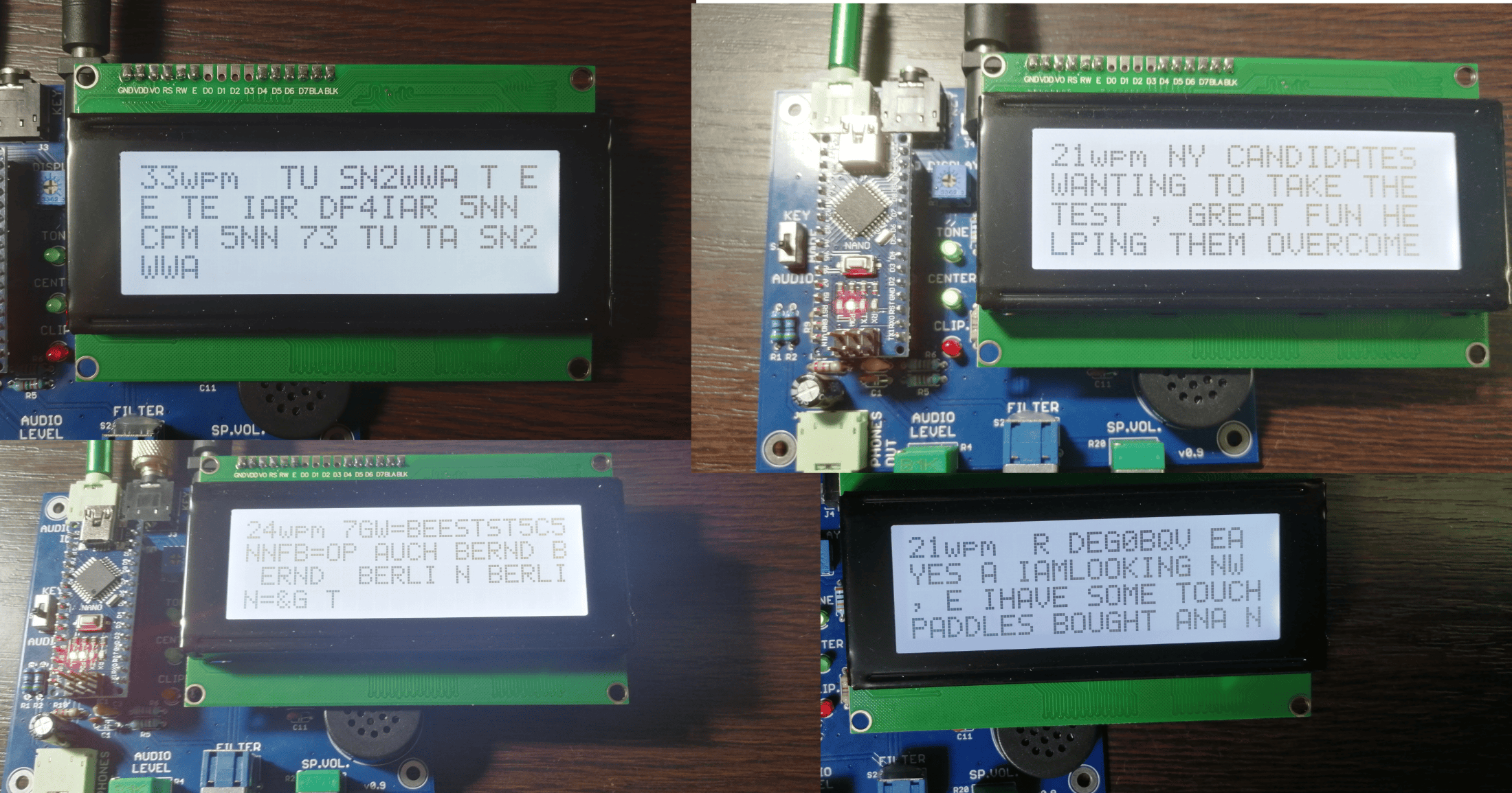
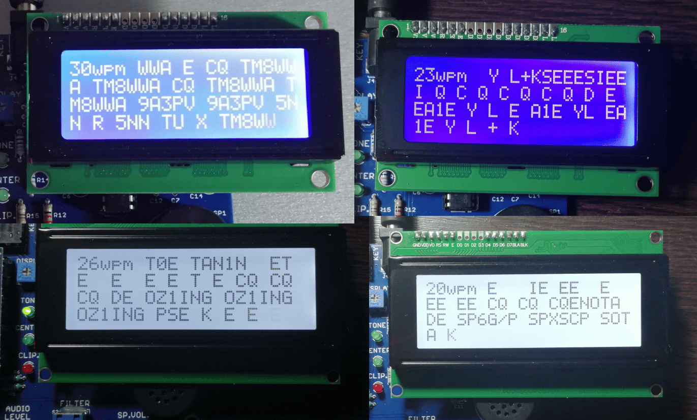
If you’re trying to pick up a weaker signal, you will probably have to add more gain and some noise will push through in the shape of stray characters and errors, but the received text will (hopefully) still make sense. Do not expect the decoder to be able to pick up all CW signals that can be copied by ear. It is inferior to a trained human operator. (But still fun.)
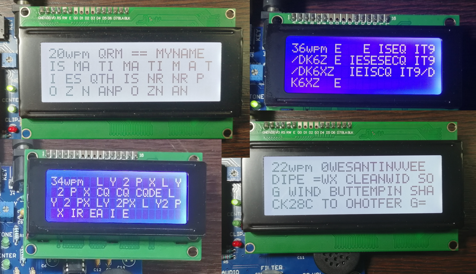
Important: Many modern HF radios feature a visual indicator that shows when the receiver is precisely tuned to the frequency of the CW signal it is picking up. They also provide a “CW PITCH” (or a similar) menu option, allowing you to adjust the frequency of the tone in the headphones when the receiver is perfectly tuned to the incoming CW signal. Ideally, CW PITCH should be set to 708 Hz, because it is very convenient to have this indication on the radio itself work in concert with the decoder.
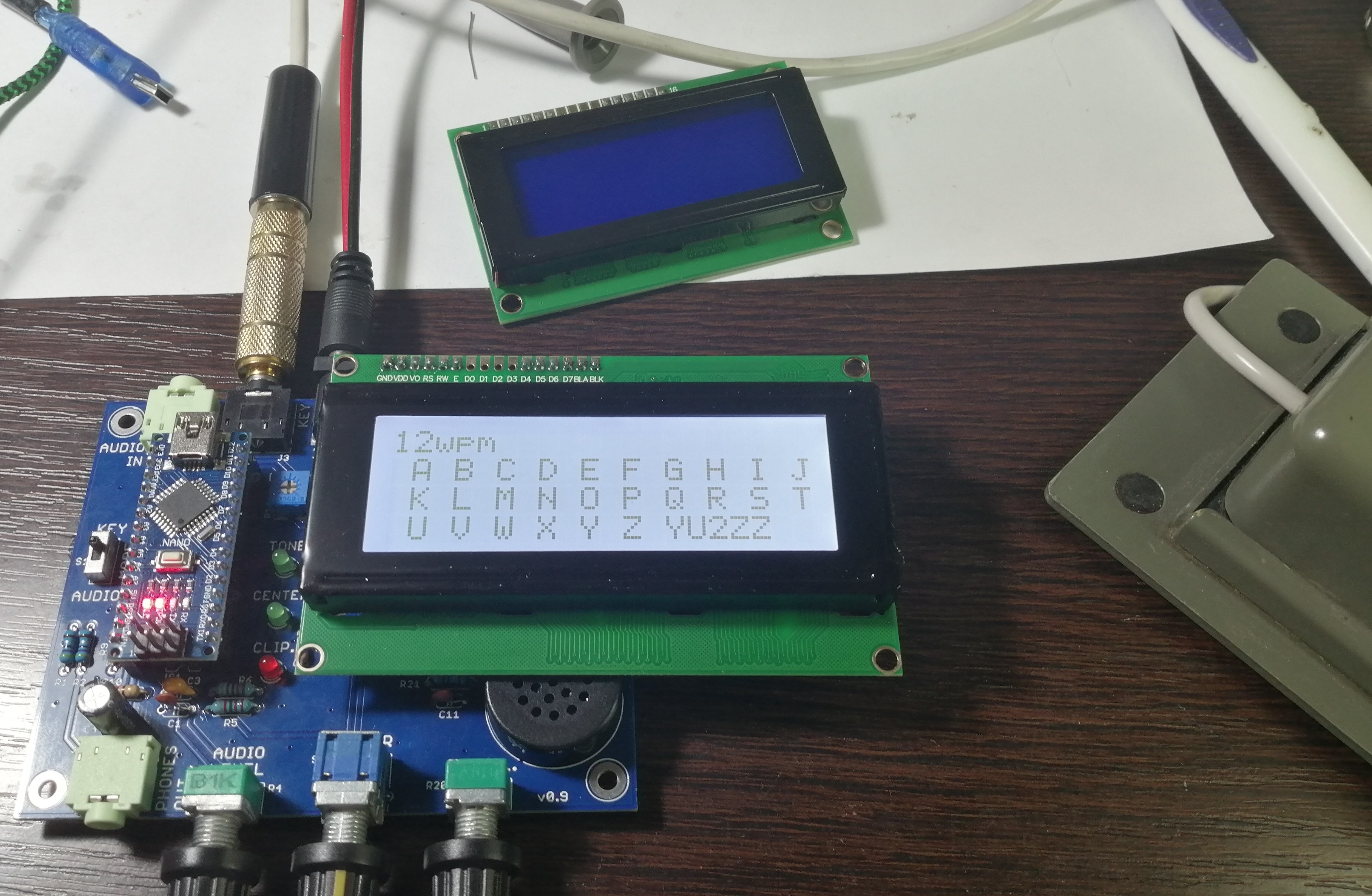
On the prototype, as soon as you plug in the CW key, the decoder automatically enters the “KEY” (training) mode. This board features a “MODE” switch, allowing the key to remain connected even when it’s not in use. The training mode functions just like it did previously: the LCD indicates the speed and the characters sent. Aside from clicks that are more pronounced at higher audio volumes, the generated tone is not unpleasant and is loud enough, thanks to an aggressive low pass filter (R17, R19, C8, C9) and the LM386 audio amplifier, respectively. There is a potentiometer for adjusting the volume. The PCB speaker is small and inefficient, but still good enough. The tone is not generated in the “AUDIO” mode.
By the way, I would recommend every CW operator, no matter how experienced they may be, to check their sending style against a machine like this, for fun. With a straight key, at lower speeds many shorten their dots to less than half of what they should be. Also, with any type of key, there is a lot of slurring going on, especially when sending CQs, our own call signs (especially prefixes), and common phrases. While receiving and decoding, we humans are guided by context and experience; when uncertain, we take our time to piece together the bits that seem to make sense. In contrast, real-time electronic decoders are clueless and in a wild hurry; even in the absence of noise, they can only decode what you sent (correctly) and not what you meant to send.
Download DSP_MORSE_1_21.ino for the hardware versions 0.9x.
Please read the first article too.
LiquidCrystalFast.h: https://www.pjrc.com/teensy/arduino_libraries/LiquidCrystalFast_1.1.zip
The PCBs for this project were produced by PCBWay. High quality boards and fast service, as always. Also, someone at PCBWay was considerate enough to choose the location for the product number so that it wouldn’t be visible on a fully assembled board (it is under the filter switch). It is not a big deal if the number is visible, not at all, but it is nice to see that someone took a moment to do it right.
Download Gerber files for the PCB, v0.91, with only minor changes relative to v0.9. For polarized components, pay attention to the markings on the board.

Links to specific components, just for identification purposes:
https://www.aliexpress.com/item/4000216967547.html
https://www.aliexpress.com/item/1005006955501818.html
https://www.aliexpress.com/item/1005008984527853.html
https://www.aliexpress.com/item/32829406275.html
https://www.aliexpress.com/item/1005005667030199.html
https://www.aliexpress.com/item/1327829833.html
https://www.aliexpress.com/item/1005008682576837.html
https://www.aliexpress.com/item/1005004486896022.html
https://www.aliexpress.com/item/1005005261273233.html
https://www.aliexpress.com/item/33013437240.html
https://www.aliexpress.com/item/1005009437588028.html


Pingback: Arduino-Based DSP Morse Decoder & Trainer For Ham Radio CW Operators | YU2ZZ ····· Elektronika. Radio. Hobi.
Pingback: Arduino-Based DSP Morse Decoder & Trainer For Ham Radio CW Operators - YU2ZZ ····· Elektronika. Radio. Hobi.