Any beginner can build this from components that can be found in an electronics scrap heap or are at least inexpensive. Yet, this device is both an interesting demonstration piece and a practical tool because it relies on cool physical principles to provide a useful function. When used with a radio receiver, it can determine the direction a radio transmission is coming from, with adequate accuracy if basic preconditions are met, over a wide frequency range from 50 MHz to 450 MHz. Its simplicity and low price make it a good entry-level device for introducing new hams to Amateur Radio Direction Finding (ARDF) as well as to practical electronics and basic antenna design.
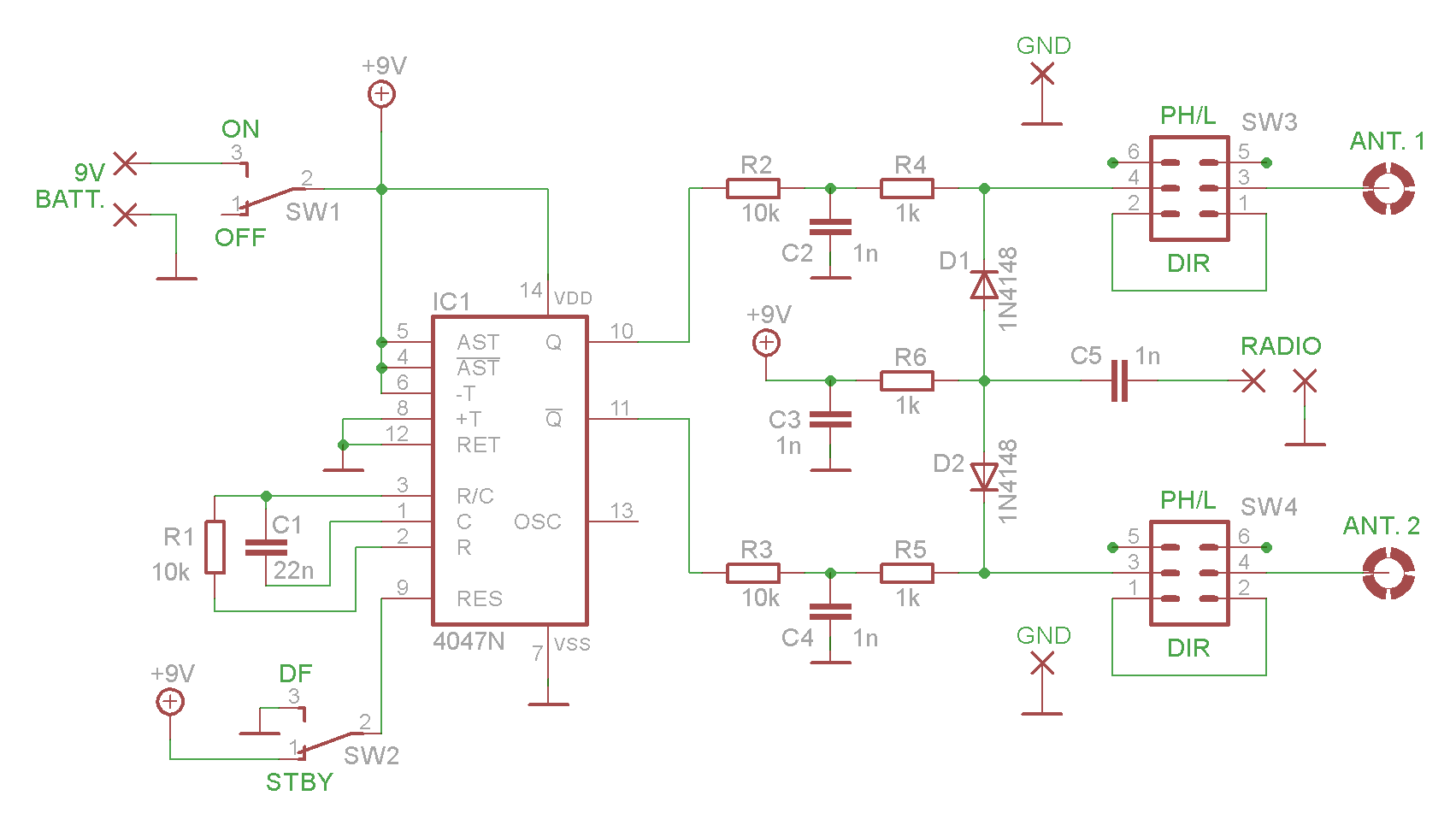
A diode will conduct RF only if it is forward-biased; that is why it can be used as a DC-controlled RF switch. The 4047 integrated circuit operates as an oscillator that alternately turns on two switching diodes at a frequency of 1,000 Hz. When pin 10 is high, pin 11 is low, and vice versa. The switching frequency is determined by R1 and C1. At any given time DC flows through only one of the two diodes, so it conducts, while the other one is blocked. Thus, effectively at any given time only one of the two antennas is connected to the receiver, and they alternate 1,000 times a second.
And that is crucial: whenever one of the antennas is closer to the radio emission source, there is a certain time difference (delay) between the signals induced in the two antennas. In the receiver, this is seen as a phase difference, is demodulated, and can be heard as a 1,000 Hz tone in the receiver audio. Only when the device is rotated so that the antennas are broadside (perpendicular) to the incoming radio waves, ensuring that they are at equal distances from the source, will there be no phase difference and no tone in the receiver audio.
The 1,000 Hz switching frequency is quite arbitrary and could be changed as desired, provided that it remains within the audio range of the receiver.

In active use, the device should be held in a vertical position, as high as possible, away from the body and other objects. It should be slowly rotated around its vertical axis until the tone has vanished. At that point the antennas are broadside to the incoming waves. This tone null should be quite narrow/sharp. The receiver can be any handheld radio.
The two antennas together look like a bow tie. I used thick copper wire terminated with solder lugs. The antenna terminals at the top of the PCB are electrically isolated and they serve only as mechanical supports. The signal reception and the direction finding depend mostly on the vertical parts of the antennas. In principle, the distance between the vertical sections could be up to half wavelength, but for these improvised wideband antennas of this particular topology – 35-40 cm is common and good enough across the very wide frequency range. (1 cm ≈ 0.39 inches). The length of each wire is typically around 48-50 cm, and the vertical sections are 15-17 cm. The wire shapes must be as symmetrical as possible.
The PCB size will allow for different handles and various ways to attach them. The one in the picture is made of plastic and relatively short (135 mm), which is OK for basic experiments. A paint-roller handle would probably be a better choice, especially if it is threaded for use with an extension pole.
All the components are low-profile and firmly fixed, so the board can be used without an enclosure, at least in dry weather.
The device is practically unusable indoors, where radio waves originating from the same source arrive at the antennas from multiple directions, due to reflections.
An extremely strong signal coming through multiple reflections can cause confusing results. If you cannot lower the power of the transmitter, you can still try to change your position to minimize reflections, or to slightly change the frequency (detune the receiver).
The initial testing and training should be done outdoors on open ground, with moderate-level signals coming from not-too-distant transmitters whose locations are known.
If the found direction seems off, most of the time it is due to reflections, or the antenna circuits are not perfectly symmetrical. If it is the latter case (more often on UHF), the error should be consistent for a given radio frequency, so you can note it and take it into account every time you use the same unit on the same channel.
The power consumption is typically less than 2 mA. The nominal capacity of the 9 V battery is 400 mAh, so it should last a very long time.
Do not transmit through the device.


SW1 and SW2 sit on improvised duct tape insulators, just in case, as there was a danger of their cases shorting across the pads on the top side of the board.
Pay attention to the orientation of the IC.


Although it is practically impossible to optimize the antenna shape for the entire frequency range, it can be fun and potentially useful to tinker in search of the best variation for a specific frequency band and a specific use case. The assumption is that the incoming waves are vertically polarized. Ideally, each antenna should be optimized so that the vertical part receives as much of the signal as possible, and the horizontal parts receive as little as possible.

Still, there are two ways to position the antennas so that they are broadside to the incoming radio waves. This creates a 180 degree ambiguity. This can sometimes be resolved by repeating the direction-finding procedure from a different location, or by using two of these devices separated by a significant distance, or…
If you add a coaxial phasing line to one of the antennas, the signals from the two antennas will be in phase only when they are in a line aimed at the source of the radio waves, with the antenna without the phasing line positioned in the front (closer to the source).
The phasing line delays the signal from one of the antennas so that the total phase difference at the receiver is 360 degrees, which is practically the same as 0 degrees. The optimal length of the phasing line depends on the frequency, with some tolerance.
L = (λ – d) * v
L = optimal length of the coaxial phasing line
λ = wavelength
d = horizontal distance between the vertical parts of the two antennas
Of course, d, λ and L must be expressed in the same units.
v = velocity factor of the coax, always less than one
For example, for the frequency of 145.0 MHz, the distance of 40 cm, and the RG-174 coaxial cable (0.66 velocity factor) – the length should be 110 cm. If this phasing line is used slightly above the planned frequency – for example, on 145.6 MHz – there will be two nulls, about 12 degrees on either side of the correct direction. (The larger the frequency difference, the larger the angle.) If it is used slightly below 145.0 MHz, there will only be a tone minimum and not a complete null. This is not a problem because the main role of the phasing line is to resolve the 180º ambiguity – “Front or back?” – and the answer to this question will still be clear in both examples.
If d and v stay the same, the length of the phasing line for 446 MHz would be just 18 cm.
The coax should be wound in a coil and attached to the back of the PCB. I used zip ties. There are holes in the board exactly for this purpose.
The coaxial phasing line is inserted in the path to one of the antennas, not both. However, by including two switches (SW3, SW4), this particular PCB design allows you to choose which antenna it will be, and at the same time, it keeps the conductor lengths to both antennas identical, except for the phasing line length. This symmetry is extremely important because the antennas’ orientation should be the only cause of the phase difference. This becomes more critical as the frequency rises and the wavelength shrinks.


Also, although it matters more on a single-sided PCB, it is better to mount the antennas on this (bottom) side of the board.

‘DIR’ stands for ‘direct’, i.e. bidirectional/wideband mode.
‘PH/L’ stands for ‘phasing line’, i.e. unidirectional/narrowband mode.

Possible improvements:
The plain silicon diodes could be replaced by PIN diodes.
You could experiment with increasing the forward bias current by decreasing the values of R2 and R3. That would lower the dynamic resistances of the diodes. In any case, R2 and R3 must remain equal.
If the device is used in a relatively narrow frequency range, the antennas could be two resonant vertical dipoles fixed on some kind of frame that can be rotated. These antennas should be connected to the PCB by equal-length coaxial cables. Even better (but more complicated), there could be two vertically oriented Yagis, each with two or three elements. The Yagis would solve the original ambiguity problem and also dramatically increase the range. Note: If an antenna circuit provides a DC path (a closed dipole or loop), a 1nF capacitor should be added in series to block DC.
See also http://www.ws1sm.com/Forms/RDF.pdf

Click here to download Gerber files for the PCB (v1.1, very slightly improved)
Click here to download the single-sided version (.pdf)
The printed-circuit boards for this project were produced by PCBWay. They could use a better Gerber viewer on their website, but everything else was excellent. High quality boards, fast. Done in 24 hours. For this project, I used an ancient version of Eagle but with the instructions from the PCBWay site I was able to create a proper .cam file and export the layout in Gerber format. For newer versions of Eagle ready-made .cam files can be downloaded from the site. KiCad has a dedicated PCBWay plug-in that streamlines the ordering process.
The company offers an especially wide range of professional/exotic PCB fabrication options, as well as other advanced services and products that students and hobbyists do not typically use. However, they are worth exploring as examples of how far technology has come and what is becoming more widely available. After all, I remember the time when multi-layer professional-looking PCBs at these prices for small-volume batches – were pure science fiction. And now everyone orders them casually without much thought. So one should go further and investigate the new opportunities on offer.
Other specific items used in this build:
https://www.aliexpress.com/item/33013437240.html
https://www.aliexpress.com/item/4000145382806.html
https://www.aliexpress.com/item/1005007084822365.html
https://www.aliexpress.com/item/1005005287108091.html
https://www.aliexpress.com/item/32958558813.html


