What this device does: as soon as you change the band on your HF radio, the antenna is automatically changed accordingly. Since there are more HF bands than available antennas, the antenna layout – which antenna to use on each HF band – is determined by DIP switches. I did consider developing a simple Android app to communicate with the board via Bluetooth, but that app would need to be maintained afterward, so… . Typically, the antenna layout isn’t changed often; the switches will do the job well.
The control board allows the operator to use one antenna on multiple bands, but not the other way around, for now. (There is a project on this blog that already offers that option by assigning a different antenna to each of the two VFOs.)

Measures have been taken, in both hardware and software, to protect the inputs from RFI. The power supply and the relay drivers are fitted with adequate overvoltage protection. A large electrolytic capacitor and several multilayer capacitors provide stability for the supply voltage.
The position of the red “Y – K” (“Yaesu – Kenwood”) DIP switch is checked by the program only immediately after the reset, and is relevant only if CAT is used.

The so-called “Yaesu BCD code” is a de facto standard for passing band data from HF radios to power amplifiers and various peripheral devices. It is supported by radio manufacturers like Yaesu, Elecraft, etc. On one of their connectors, these radios provide the current band information in the form of a four-bit code that can be used to switch antennas, filters, etc. In the manuals, these four lines together are usually called “BAND DATA”, while individually they are marked “A”, “B”, “C”, “D”. Some power amplifiers also support this standard and have appropriate BCD outputs.
With Kenwood radios, the information about the currently selected band can be obtained via CAT, but relevant CAT commands may differ from model to model. The Arduino program presented here supports the TS-590, TS-890, TS-480. The radio communicates with the control board through its COM-port, i.e. RS-232. The control board software also supports CAT communication with newer Yaesu radios, such as the FTDX-10, FTDX-101, FT-991. (It was just easy to implement. Also see the “Y-K” DIP switch.)
Typically, Yaesu radios will use the “BAND DATA” inputs on the control board, while Kenwood radios are connected via CAT (RS-232).
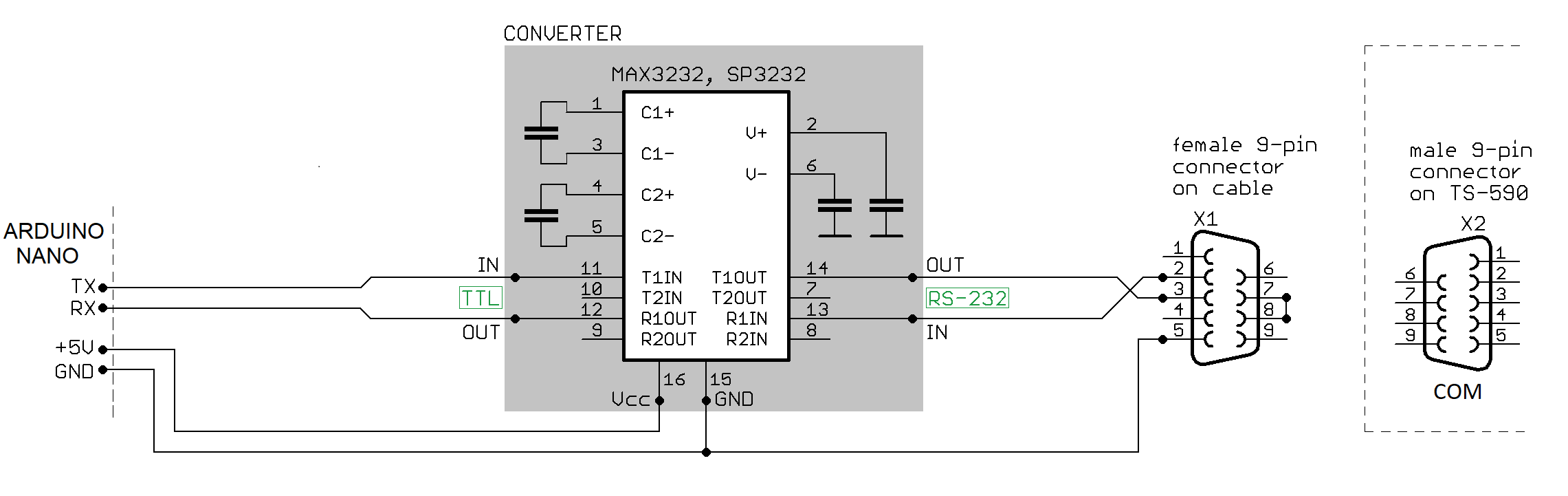
The diagram shown will probably work for many modern models of both Kenwood and Yaesu, but:
BE SURE to CHECK the MANUAL for YOUR RADIO MODEL FIRST. Be careful.
Note that this control board includes the TTL-RS232 converter.

The schematic isn’t really complex. The MAX232 is used for communication via RS-232, and the Arduino Nano manages everything. The antenna switching relays are driven by the Darlington low-side drivers inside the ULN2003. (The relays are in a separate enclosure.) The 5 V voltage for the Arduino, the display and the MAX232 comes from a small DC/DC converter, a drop-in replacement for the 7805 regulator. It is possible to use a “normal” 7805, but it would need a heatsink.
Program the Arduino Nano BEFORE you plug it in, i.e. while it’s not connected to the MAX232.

A minimalist version is possible – without the display and the buzzer. It would simplify the construction and potentially reduce the dimensions of the enclosure.


On Yaesu radios, both “BAND DATA” and “TX GND” pins for power amplifier control are usually in the same connector. That is why here the “TX GND” wire enters the enclosure inside the same cable as the BCD wires, but is then routed to an RCA connector on the back panel, so that it is again easily accessible. For the CAT connection, I mounted a DB-9 male connector on the back panel, with pins 7 and 8 shorted. For the BCD and TX GND inputs I used a 6-pin GX12 connector.
The cable to the radio should be short and shielded.
The control board and the relay box are connected with a normal straight-through UTP cable. The pinout:
1 – Relay coil 1 (Antenna 1)
2 – Relay coil 4 (Antenna 4)
3 – Relay coil 2 (Antenna 2)
4 – positive voltage for the relay coils
5 – positive voltage for the relay coils
6 – Relay coil 3 (Antenna 3)
7 – Relay coil 5 (Antenna 5)
8 – positive voltage for the relay coils

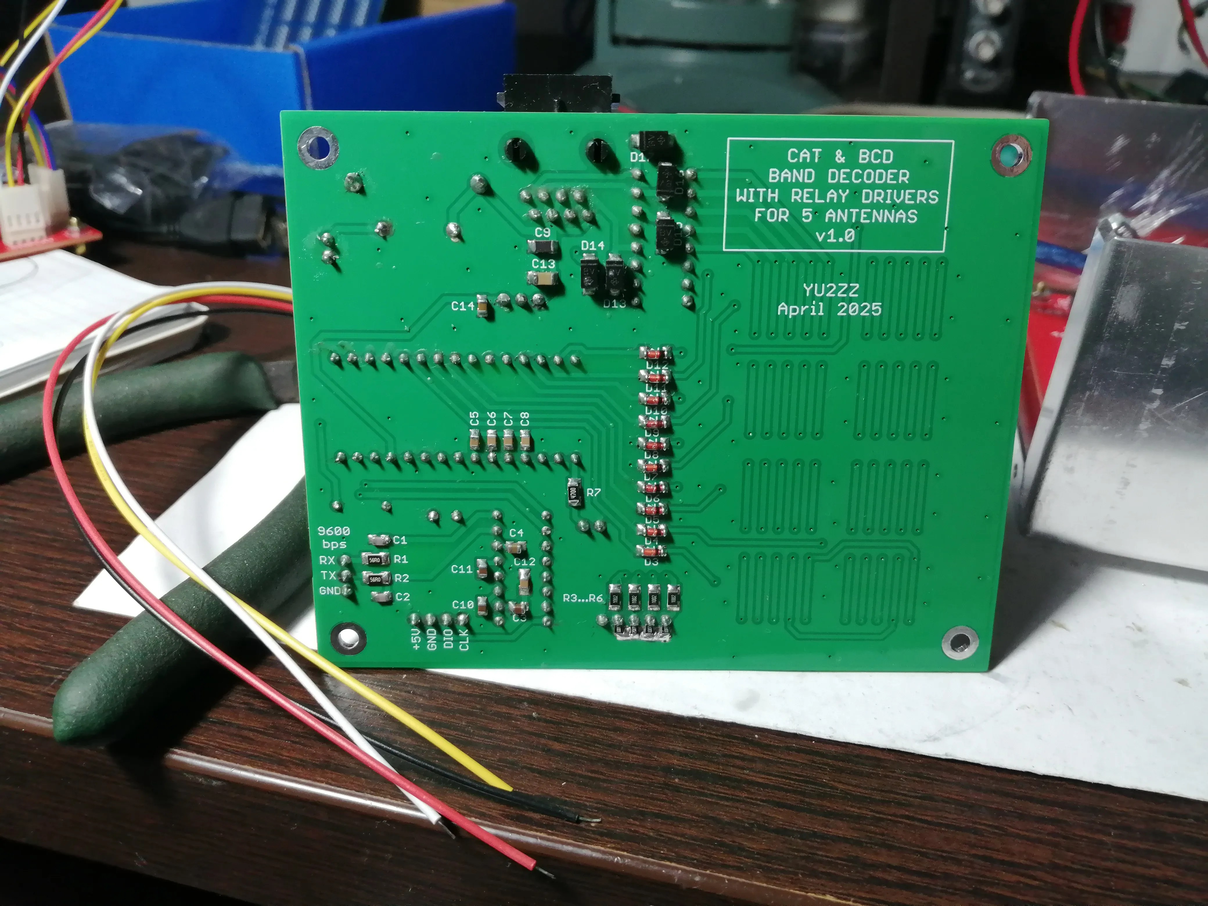
The black arrow points to the pad where the radio should be connected.
One side of each relay coil is connected to the positive voltage rail. A relay is activated when a Darlington driver inside the ULN2003 (within the control box) connects the other side of the coil to the ground. Only one relay is energized at any given time. Without power, all antennas are connected to the ground via the NC (“normally connected”) contacts.

The relays are Schrack RT314012, Finder 4161 or similar 12 V models. They can handle maximum legal power. The effect on the SWR is negligible on HF. The varistors are 18-22 V DC, 5 mm pitch.
The board sits on three or four 25 mm brass standoffs.
As a rule, commercial solutions have the SO-239 connectors directly soldered to the PCB. I suppose that is easier and cheaper for mass production, but over time, the mechanical stresses cause PCB delamination, and the electrical contact is lost. The homebrew solution shown in the picture – is actually more reliable. Also, the front panel will be held by one additional screw on either side, so it moves very little.
A supply voltage of 15 V DC is a safe bet for longer UTP cable runs, because 1.5 V is lost in the control board itself. The total current draw at 15 V is about 80 mA.
The UTP cable can be LONG, tens of meters easily, provided it is of decent quality. A relay coil draws less than 40 mA. Also, the positive voltage for the relay coils is sent through three conductors connected in parallel, which lowers the total cable resistance and the voltage loss.
With 12 V relays, in extreme cases, the power supply voltage could be raised to 16 V to compensate for the voltage drop in the UTP cable, but that is hardly ever necessary.
If you prefer 24 V relays: D2, D13 to D17 and the varistors should have appropriately higher voltage ratings; that is all.

In principle, this unit could also be used with a different control board, and vice versa.
Both enclosures must be grounded. Both coaxial and UTP cables should be disconnected during stormy weather.

The RJ-45 (8P8C) connector is the same on both the control board and the relay box.
The Arduino program can be adapted to support more radios, using CAT. For relevant CAT commands, see your radio’s CAT manual (or “PC Command Manual”).
Download control board Gerber files
Download relay box PCB Gerber files
P.S.
If, for some reason, your radio cannot be connected to the control board directly in either of the two ways already mentioned, there is another solution: logging programs (N1MM, Win-test, DXLog etc.) typically provide BCD band data on the computer’s LPT port, which is – true – rarely seen these days, but can be added. As a rule, USB-to-LPT converters will not work for this application, so you should try a PCI-LPT adapter card instead.
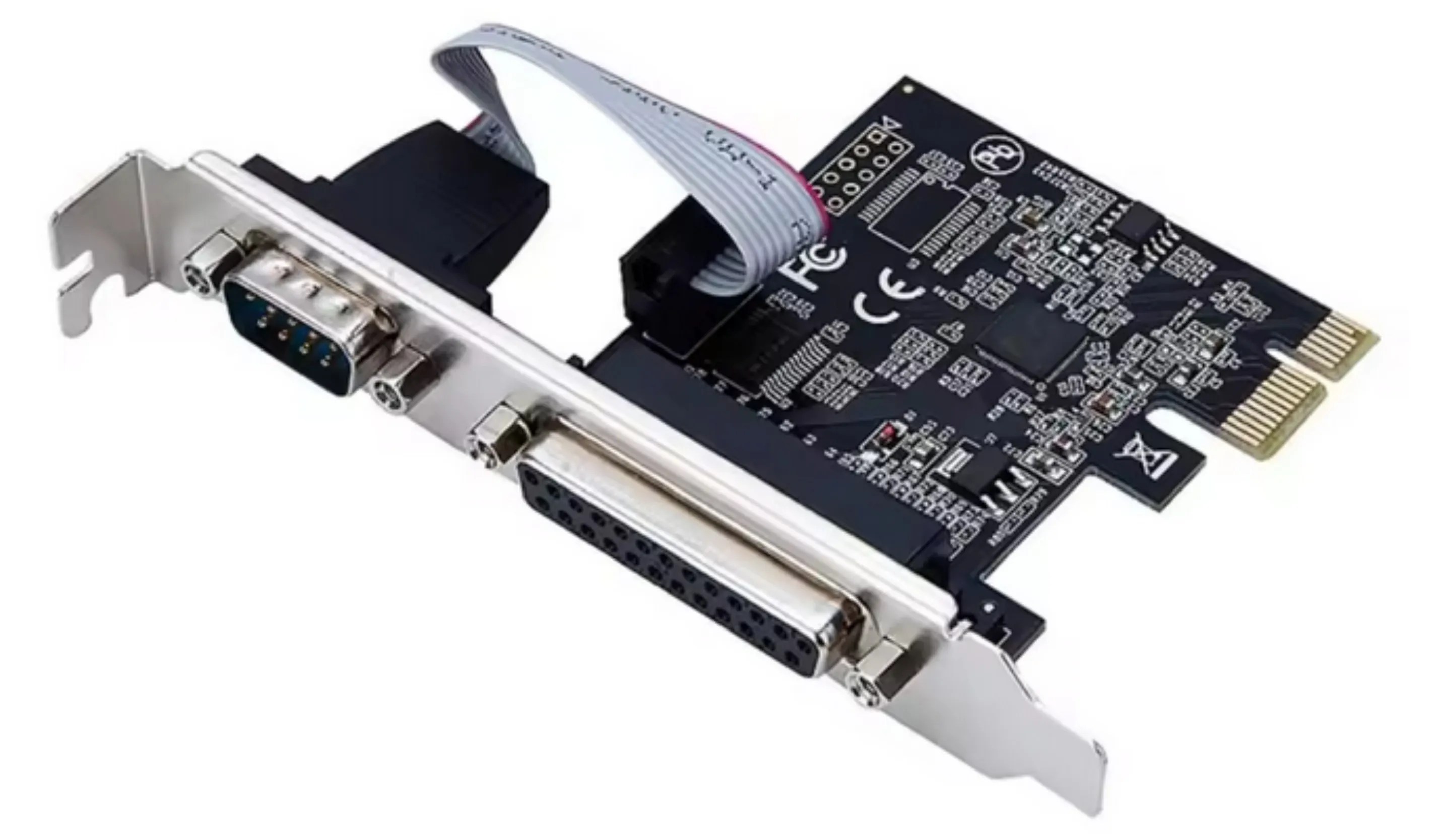
I successfully tested this card with N1MM logger and Win-test under Windows 10 (64bit). It is based on the AX99100 chipset. The port address is EFF8. When everything is set properly, pins 2, 7, 8, and 9 in the DB-25 connector provide the four-bit code indicating the band currently selected in the program. (Pin 2 is bit “A” etc.) The logical “one” is 3.3 V. Drivers are available on the Internet.
With DXLog, it worked only under Windows 7/32bit. The port address is E010. Maybe it has something to do with the drivers; I didn’t spend too much time investigating.
In any case, consult the program documentation first for instructions how to set the LPT port options.
The card shown also features a COM port connector, which I did not really need. There are models based on the same chipset that offer an LPT (DB-25) connector only.


