After you finish reading this article, please also read the sequel:
This real-time Morse decoder uses the Goertzel algorithm to detect a CW tone of 708 Hz. In order to better isolate the useful signal, the program introduces comparing the magnitudes for three frequency bins – the central one and two adjacent ones on both sides.
The program then analyzes the detected tone patterns in order to recognize and decode Morse characters.
The decoding is flawless if the input signal is itself flawless in every aspect. The speed can exceed 50 standard words per minute (wpm). However, on the always noisy HF bands the decoder is clearly inferior to a trained human ear. Still, at any given time one will find real CW transmissions that can be decoded with some success, although the results may vary from a few clear words in a pile of gibberish – to 100% accurate text. Unusual sending styles also confuse the decoder.
The purpose of this Morse decoder is not to discourage operators from learning Morse code but, on the contrary, to stoke their curiosity and give them a fun learning experience.
The decoder automatically adjusts to the transmission speed. When there is a sharp change, it will take a few characters to determine the new wpm, but that is not an issue. The internal speaker outputs a 708 Hz tone repeating the detection pattern, i.e. Morse characters, if all goes well.
The program provides three levels of simple filtering. High speeds require filter level 0, i.e. no filtering at all. Filter level 1 is mild and should be used for speeds up to 36 or so wpm. Filter level 2 should be good for speeds below 25 wpm (the numbers are only approximate). A wrong choice of filter level will mess up decoding.


On the other hand, the letter ‘F’ made it, barely.
The tone detection algorithm is very sensitive to any frequency offset. The detection will work for a range of frequencies, but it will perform best when the tone is exactly right. The green LED flickers when it is close, but that indicator is not nearly good enough. The RIT/RX Clarifier on the radio should be used at all times, tweaking the frequency for that sweet spot and the best result.
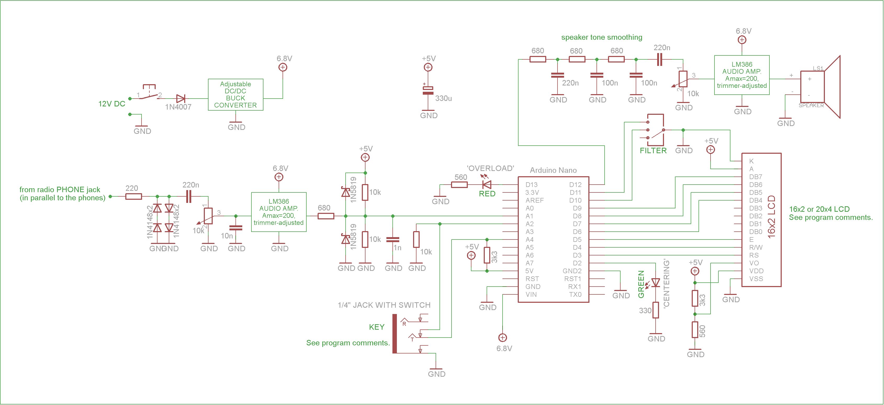
The input signal level should also be adjusted for optimum performance. The red LED shows when audio peaks are getting pretty high, close to clipping (but not necessarily there). Currently this LED lights up at around 4 Vp-p. By the way, in this specific implementation (the second schematic below) the analog input A1 is protected against overvoltage.
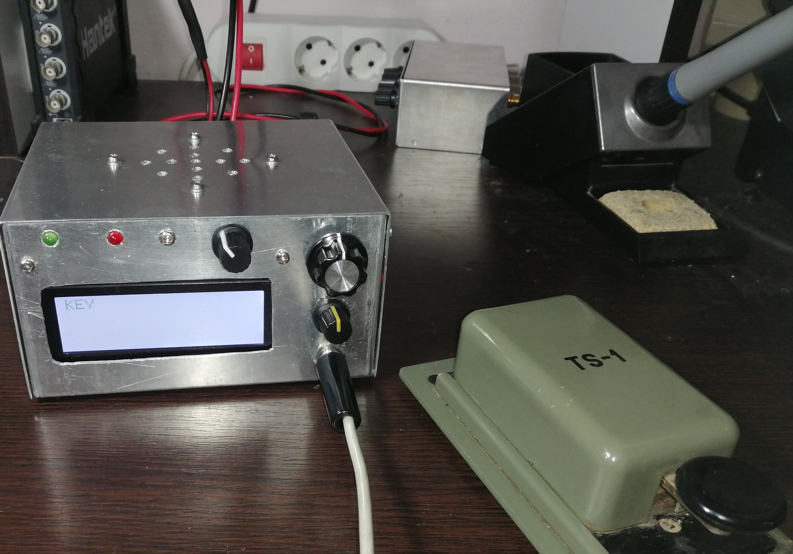
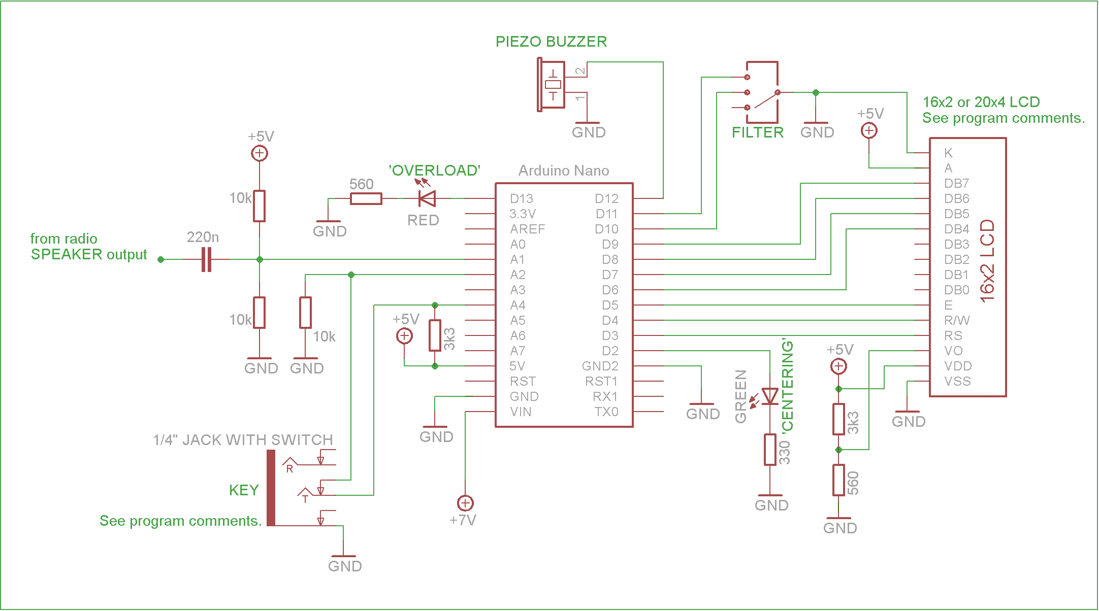
The detection works best if the input signal’s amplitude is large enough so that the (almost) full DC range of the ADC can be used.

There is still a lot of experimenting and tweaking to be done.
Download the Arduino program: GOERTZEL_ZZ_v1_0.ino
LiquidCrystalFast.h: https://www.pjrc.com/teensy/arduino_libraries/LiquidCrystalFast_1.1.zip
You can also download version 1.1 that has been shown to perform marginally better in certain situations involving weaker signals and QSB. For example, it can salvage the lost letter ‘Z’ from the audio snippet shown above. It is in the tinkering phase and may be updated sporadically.
Please read the follow-up article.
The initial idea for the decoder came from here:
http://www.oz1jhm.dk/content/very-simpel-cw-decoder-easy-build
I studied the original program but ended up writing essentially a new one. The hardware setup is also different. Anyway, big thanks to OZ1JHM/OZ8CW.


Pingback: Arduino-Based DSP Morse Decoder and Trainer, on a Custom PCB | YU2ZZ ····· Elektronika. Radio. Hobi.
Pingback: Arduino-Based DSP Morse Decoder and Trainer, on a Custom PCB - YU2ZZ ····· Elektronika. Radio. Hobi.