Tested with the Kenwood TS-590SG. Reads data from CAT, switches antennas automatically. Supports ten bands and two antennas per band.

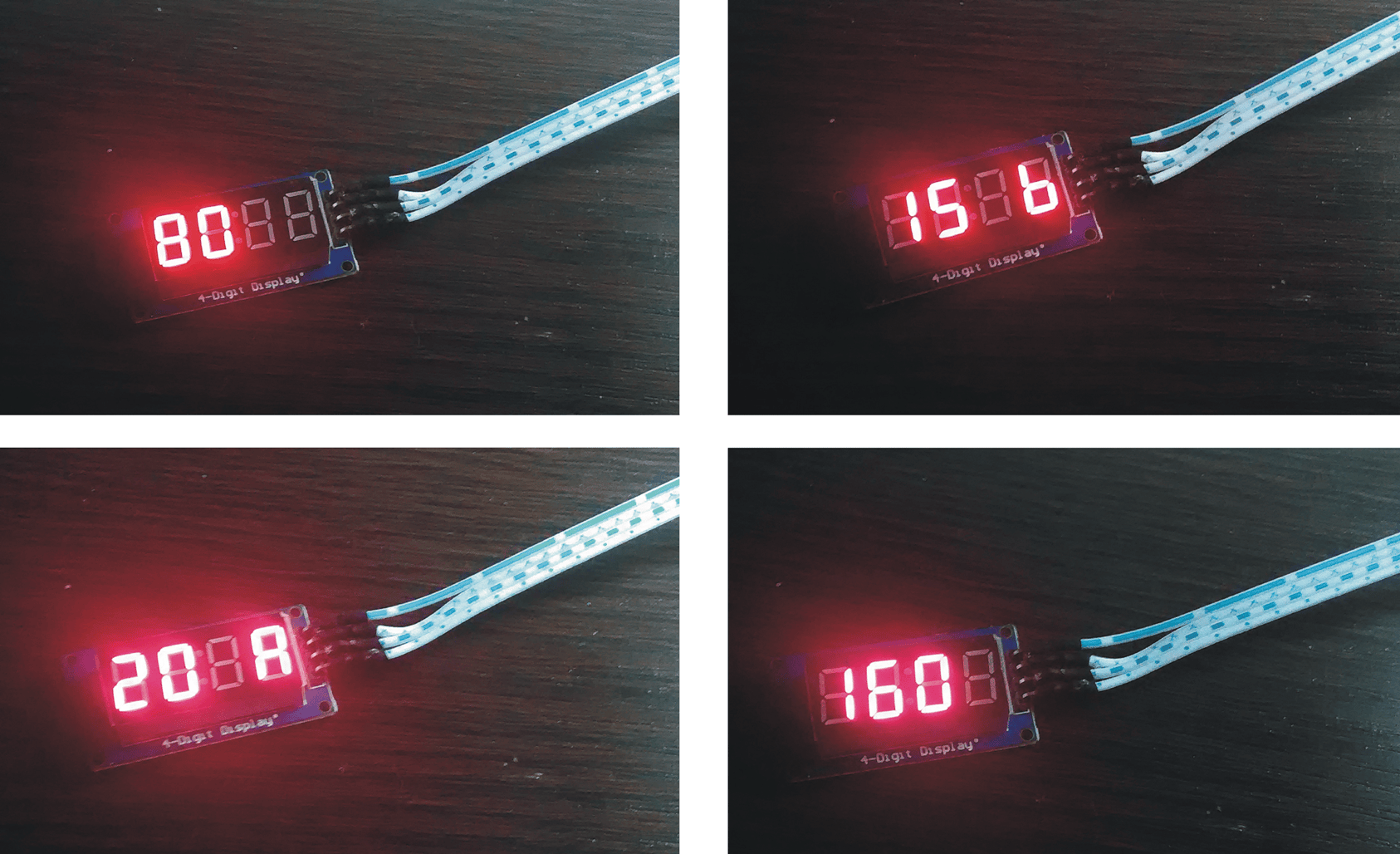
Each time there is an automatic antenna changeover, the device sounds a confirmation in Morse code indicating the newly selected antenna, for example: “160”, “20A”, “20B”, “15”, “12” etc.
Selecting the other antenna for the same band by switching VFOs on the radio may not be a perfect system, but it does the job. Still, if you prefer, you can install the jumpers and use only one antenna per band.
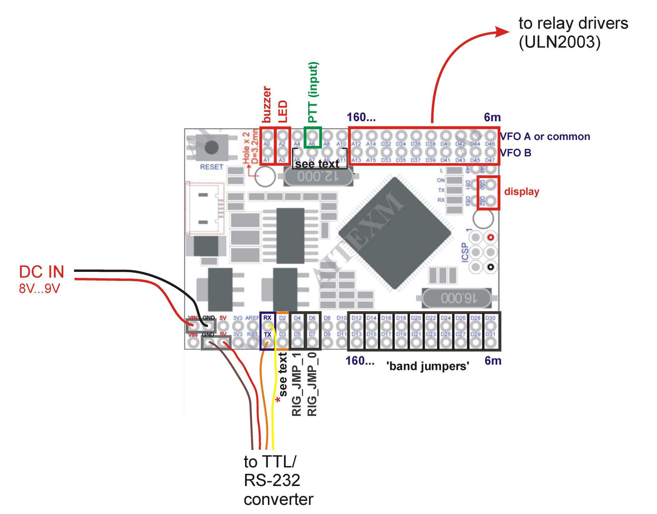
The output for the passive buzzer is on pin A0. The positive end of the LED should be connected to A2. The pins right below these (A1 and A3) are outputs set to LOW so that the negative ends of the buzzer and the LED can conveniently be connected to A1 and A3, respectively, using Dupont or similar connectors. A current-limiting resistor of at least 150 Ω should be connected in series with the buzzer. If a piezo-buzzer is used, connect another 3.3k…4.7k resistor across the buzzer. The LED must have its own current-limiting resistor of 330 to 680 Ω. While there is good communication with the radio, the LED is continuously on, turning off only for 400 milliseconds at each automatic antenna changeover.
If the buzzer is not connected, the program will skip the Morse code message altogether, so no time will be wasted between CAT polls. (The LED’s 400 ms blink is non-blocking anyway.)
The PTT input is on A6. Automatic antenna switching is disabled while A6 is LOW. DO NOT directly expose this pin to the potentially harmful voltage on the PTT line. A protection circuit must be used.
Please check the datasheets and examples for the ULN2003 and/or ULN2803. They are extremely easy to implement: the outputs from the controller board should be connected directly to the ULN2x03 inputs. The ULN2x03 outputs drive the relays that switch antennas on and off. That’s about it. The ULN2x03 outputs can be connected in parallel for multiband antennas. There are also off-the-shelf driver modules with these ICs or MOSFETs, with up to 16 individual drivers.
The device should also work with the Kenwood TS-890, which uses the same CAT commands as the TS-590. By installing or removing the jumpers RIG_JMP_0 and RIG_JMP_1 you can adjust CAT protocol parameters to enable communication with newer Yaesu radios (see program comments). That option hasn’t been properly tested, except for a brief and successful run with a Yaesu FT-991A. On the other hand, Yaesu radios have standardized ‘BAND DATA’ (BCD) outputs that are simpler to work with than the CAT interface. For all brands there is also the potentially deal-breaking question of available CAT connectors on the radio.
The current band is also output in the Yaesu BCD format at pins A11, A9, A7, A5 (A, B, C, D, respectively).
After a reset, if there is no communication with the radio all outputs will be LOW (no antenna selected), the display will be off and the LED will give very short flashes while the controller is trying to establish connection with the radio. After the first successful data exchange over the CAT interface, the LED and the display will turn and stay on and one of the antennas will be selected. The controller will continue to poll the radio for its current frequency and VFO and will switch antennas when necessary. For the situation when the radio stops responding, see CONNECTION_TIMEOUT_SET and CONNECTION_TIMEOUT_SECONDS in the program.
All station setups are different, so many different usage scenarios are possible, depending also on whether the controller is used for remote or local operation etc. It doesn’t even have to do antenna switching at all, as other applications are possible.
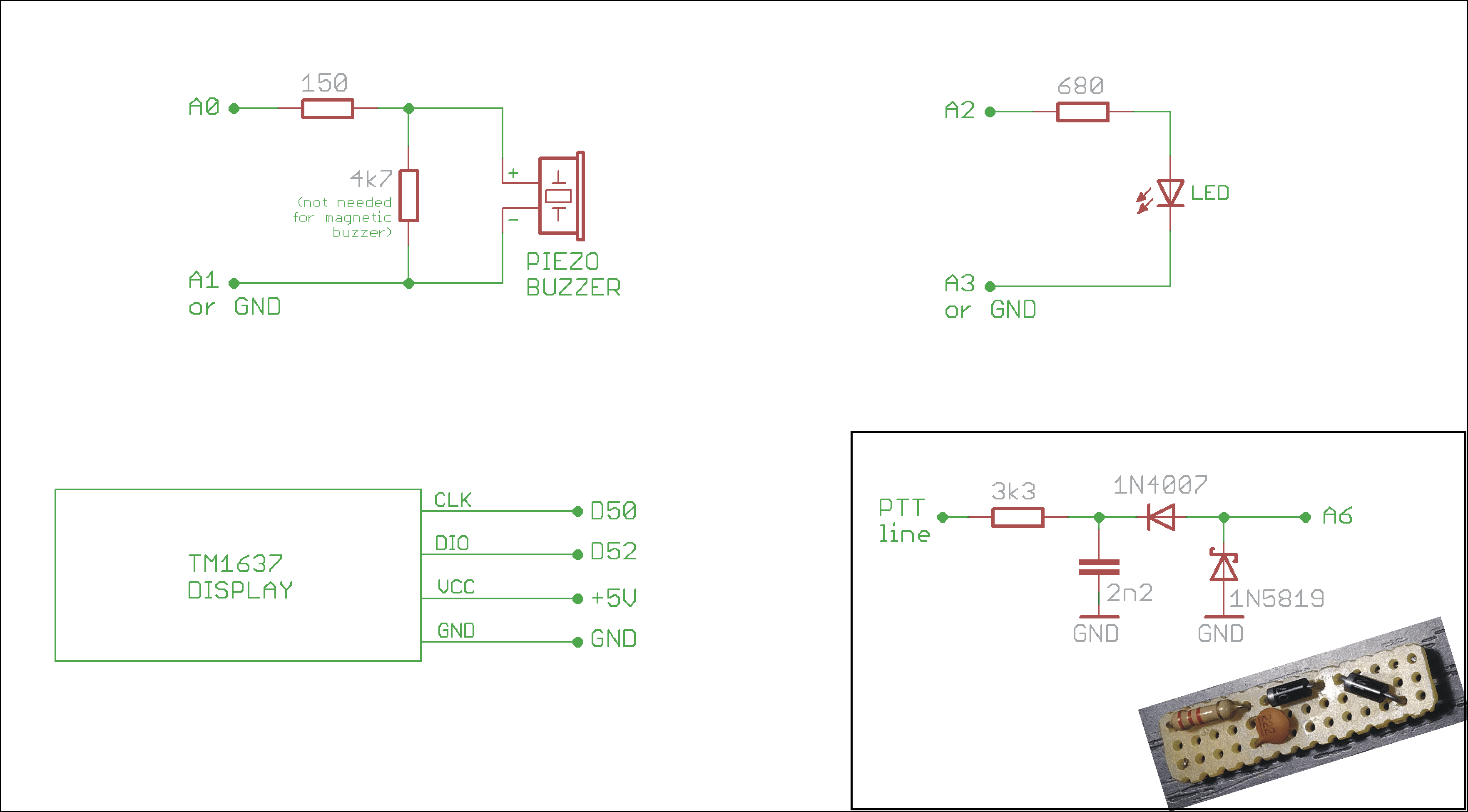
All pins needed by the display are also accessible through the ICSP header. Each of the three indicators is in fact optional, the controller will perform its main function with or without them.
* If you want to retain the possibility of independent manual switching, you can use a rotary switch. Its pole terminal should be connected to GND and its output terminals should be wired in parallel with the relay driver outputs – except for the output terminal no. 1, which should be connected to pin D2 on the controller board. So the first position of the rotary switch would enable automatic switching, while the other positions would directly select a specific antenna each. In manual mode (while D2 is not at GND, i.e. in any position of the switch except 1) all outputs would be LOW (off). The LED, the display and the BCD output would also be off in manual mode. For normal automatic operation, a jumper MUST always be in place across D2 and D3 (the red jumper in the photos) – or you can set MANUAL_OPTION_ALLOWED to NO in the program.

KEEP the on-board voltage regulator cool: if the device is to be supplied via pin Vin on the MEGA 2560 PRO, use 8-9V DC, not 12V. Alternatively you can apply 5V directly. The device will draw up to 70 mA, plus up to 50 mA for the 0.36″ display.
DO NOT overload the board’s outputs. There is no need to draw more than a few milliamps per pin.
BEWARE of RFI and ESD when planning and executing the wiring.
MEGA 2560 PRO datasheet
TM1637 Display User Guide
TM1637 Display Arduino Library
ULN2003 Datasheet
ULN2803 Datasheet


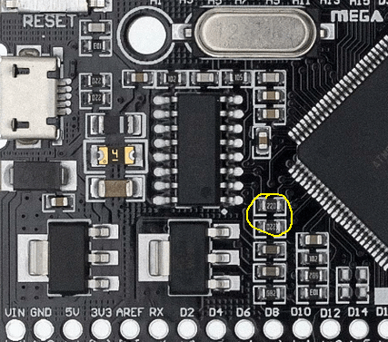
IMPORTANT NOTE: on some MEGA 2560 PRO boards these two resistors (see picture) are 22 Ω, which is too low and may cause DAMAGE when a TTL/RS-232 converter or any other device is connected to the board’s RX and TX pins. These are the resistors in the data lines between the microcontroller and the USB chip. One of them is more critical than the other, but replace both of them with 1k or 2k2 before powering the board. Later in operation the built-in RX LED will blink only when the microcontroller is communicating with the USB chip (and the computer) and will not light up while the board is receiving data from the radio. And, as always, you will have to temporarily disconnect the outside device from the board in order to program the microcontroller through the board’s USB connector.


Pingback: ‘CAT-to-BCD’ Band Data Converter for Kenwood TS-590, with Arduino Nano | YU2ZZ ····· Elektronika. Radio. Hobi.